Engineering Review: LP Thread vs. Hammer Union in Permanent 5K Wellhead Manifolds
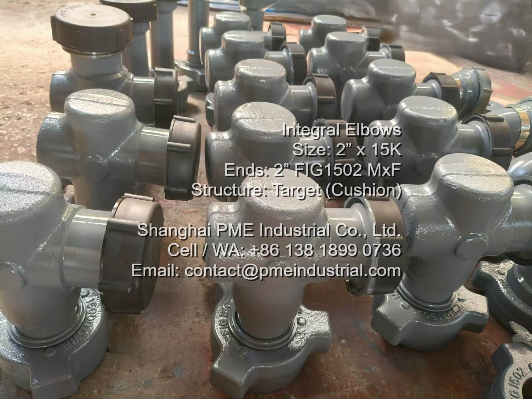
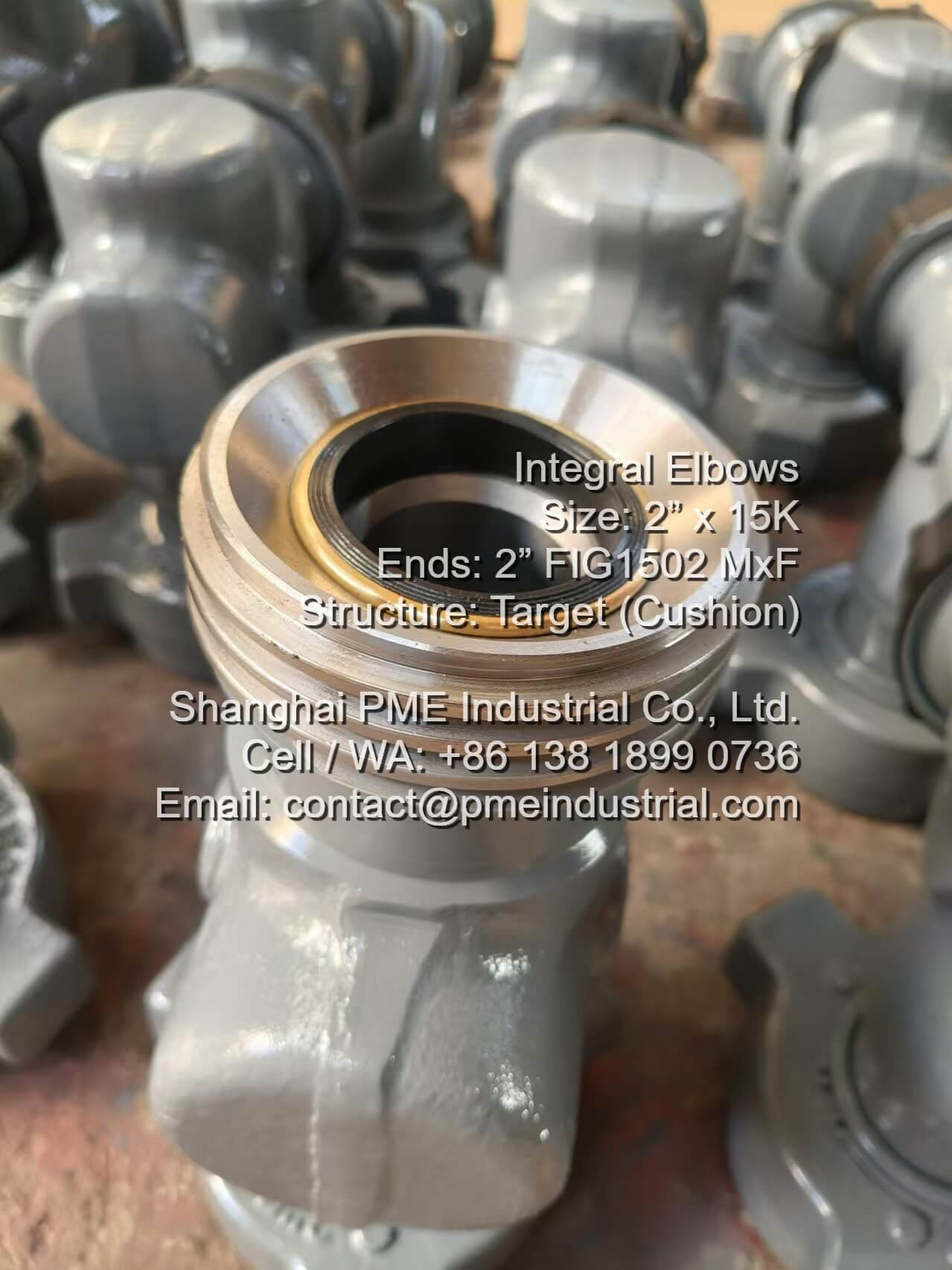
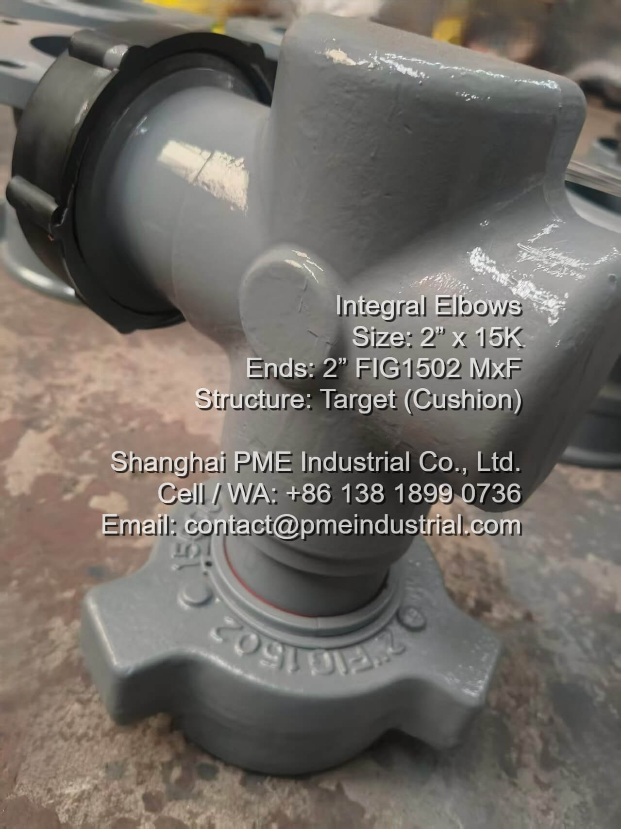
In temporary flowlines, rapid setup and teardown are prioritized, making hammer unions (like the 2" FIG 602) the industry standard. However, when specifying flow control assets for permanent upstream production manifolds and offshore wellhead skids, dynamic structural harmonics present a major challenge. Standard elastomeric union gaskets can degrade under persistent vibration, leading to high-pressure leaks. To resolve this, petroleum engineers are turning to robust threaded alternatives. Implementing a certified 2 inch 5000 psi lp thread plug valve provides an interference metal-to-metal connection that eliminates localized micro-leak pathways.
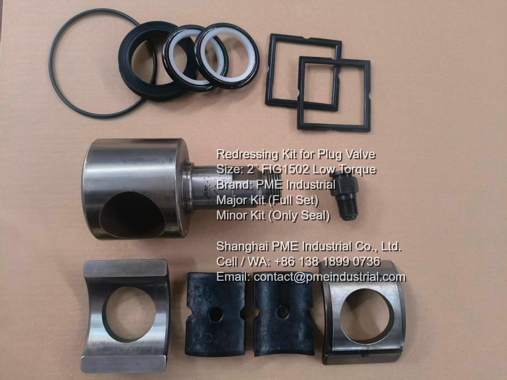
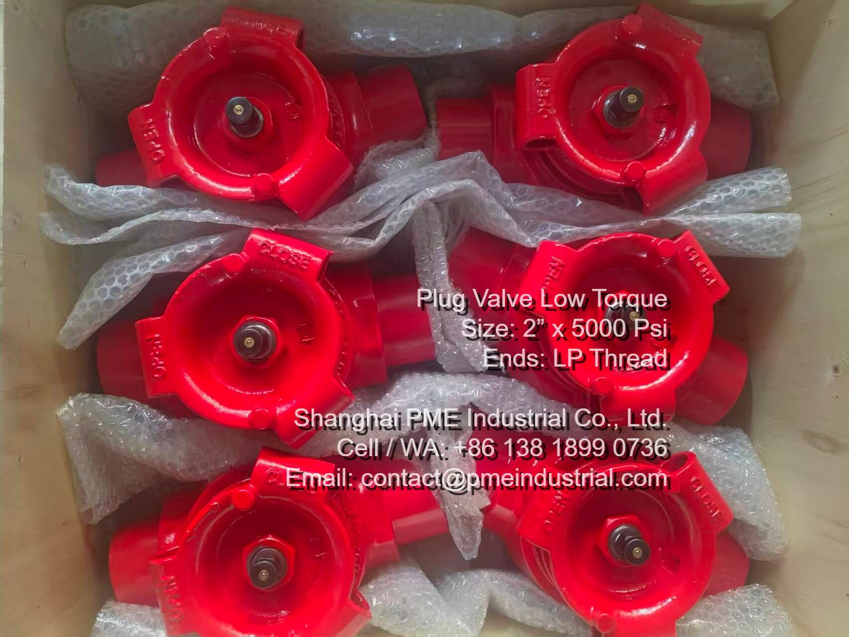
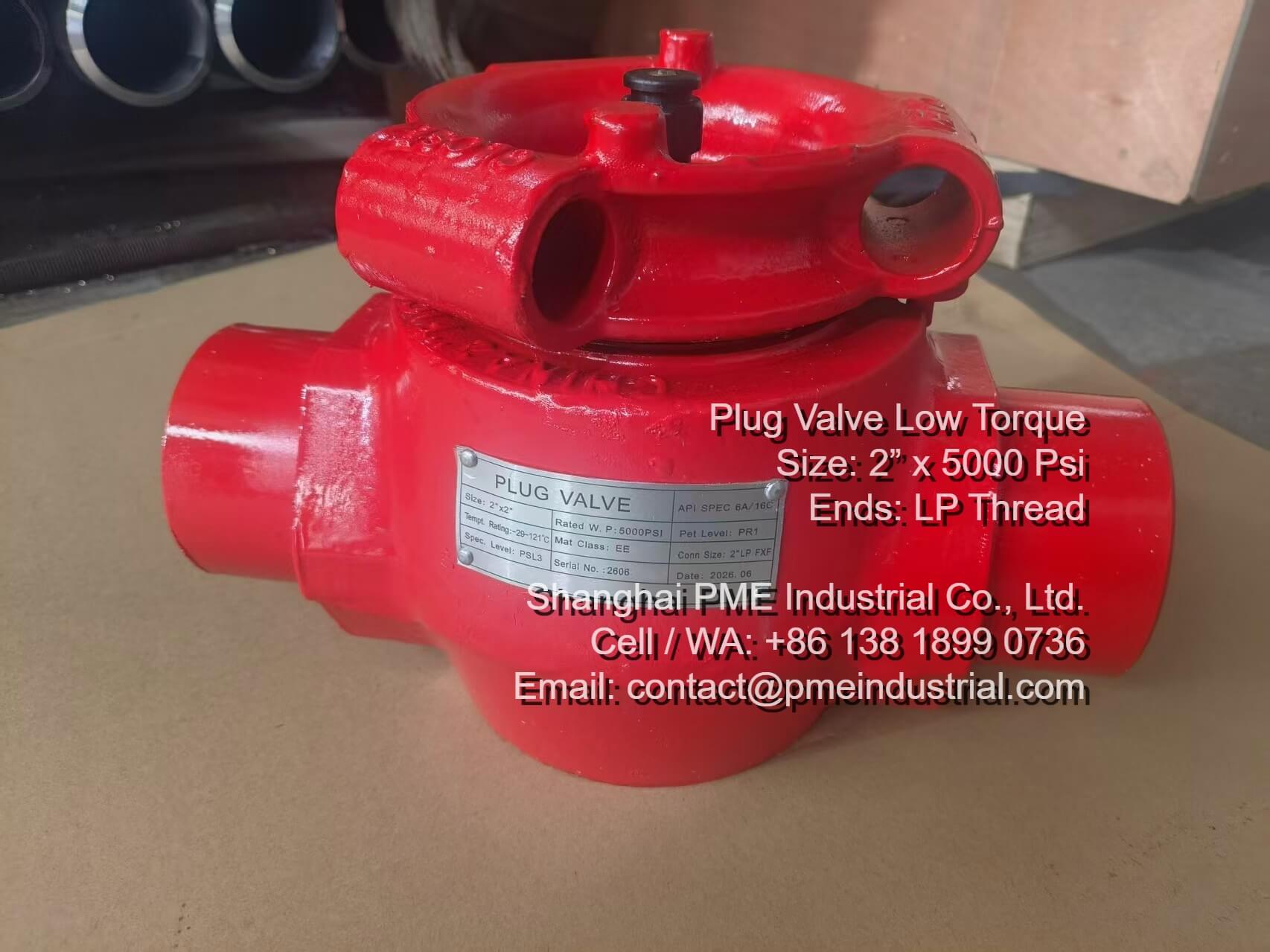
PME Industrial has successfully completed a specialized batch of API 6A 5,000 PSI CWP plug valves featuring 2-inch female Line Pipe (LP) threaded connections. Fully engineered for sour gas (H2S) environments and compliant with NACE MR0175 standards, these low-torque valves are designed to fit flush within tight manifold layouts where traditional bulky union nuts lack swing clearance.
Export Ocean Wooden Case Packaging
API 6A Serial Tracking Plate
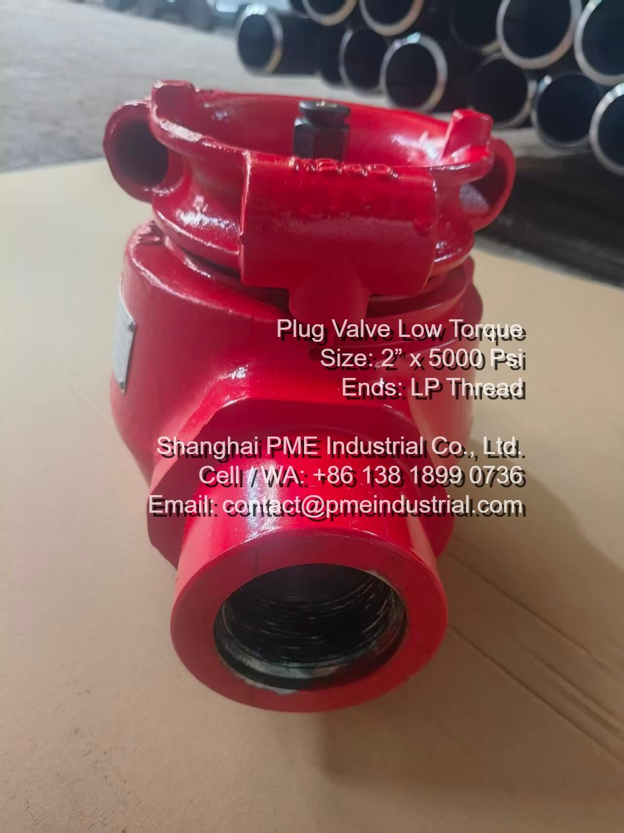
Precision Female LP NPT Porting
Why Line Pipe (LP) Thread Interfacing Excels in Permanent Service
When standard high-pressure flowlines use union configurations, dynamic vibration from pumps can lead to backing-off or gasket extrusion over time. PME's engineered line pipe thread plug valve series utilizes female LP thread ports that conform strictly to ANSI/ASME B1.20.1 NPT metrics. This creates a secure connection that distributes stresses evenly across the thread roots. It is highly suited for offshore rig cabins and permanent production blocks where space is limited and long-term seal integrity is required.
Engineering Verification & Testing Safeguards
To meet the requirements of deep-well exploration in Southeast Asia, every 5,000 PSI CWP plug valve undergoes rigorous quality control. This includes a full 7,500 PSI hydrostatic shell test to verify structural integrity. Combined with low-torque dry-film internal plug coatings and sour service trim, this range delivers dependable isolation with minimal maintenance.
Rig Sourcing Specifications
| Parameter Class | Detailed Design Specifications (API 6A Compliant) |
|---|---|
| Nominal Port Diameter | 2" Inch Straight-Through Bore (minimizes flow turbulence) |
| Cold Working Pressure (CWP) | 5,000 PSI (34.5 MPa) Working Pressure | 7,500 PSI Hydrostatic Test |
| End Connection Type | 2" Female Line Pipe (LP) NPT Thread Connection (ASME B1.20.1) |
| Environmental Compliance | NACE MR0175 / ISO 15156 Sour Gas Service Compatibility |
Get Factory Estimates for 5K LP Plug Valves
Shanghai PME Industrial manufactures custom-spec API 6A plug valves with full mill test reports (MTR), hydrostatic logs, and NACE certifications. Visit our product portal to connect with our engineering team.