
Engineering Analysis: Optimizing Terminal Line Blanking in Medium-Pressure Piping
In marine bunkering terminals, petroleum processing plants, and fluid transfer facilities, isolating branch lines or terminating manifold runs securely is a frequent engineering requirement. Piping designers often evaluate whether to use traditional blind flanges, threaded pipe caps, or specialized hammer union fittings when closing off terminal lines.
Deploying makeshift threaded caps or bulky blind flanges on medium-pressure lines introduces additional bolting points, increases potential leakage risks, and extends assembly labor during maintenance. To address these operational challenges, utilizing a purpose-built 4 inch FIG 207 Blanking Union provides a streamlined, pressure-rated closure mechanism designed for 2,000 PSI CWP standard service.
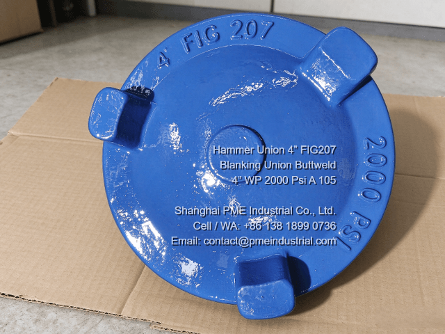
Figure 1: External view of the forged blue FIG 207 blanking cap displaying 2000 PSI ratings and hammer lugs.
1. Structural Advantages Over Conventional Blind Flanges
When comparing terminal closure options in 4-inch piping spreads, the FIG 207 configuration offers distinct mechanical benefits:
- Elimination of Bolt-Up Flanges: Standard flanged blind connections require multiple bolts, gaskets, and precise torque sequencing. A hammer union blanking cap uses a rugged wing nut interface for rapid manual or hammer makeup.
- Compact Manifold Footprint: In skid-mounted bunkering units or tight offshore deck spaces, a blanking union occupies significantly less physical envelope than a corresponding ANSI blind flange assembly.
- Component Interchangeability: Because FIG 207 shares matching ACME thread geometry and male sub dimensions with standard FIG 206 lines, operators can easily convert existing flow lines into closed terminals.
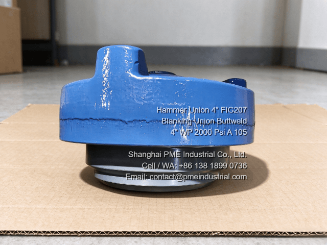
Figure 2: Side profile showing the blue blanking cap assembled over the grey male sub structure.
2. Material Integrity & Butt Weld End Preparation
Manifold reliability depends heavily on base metal selection and end connection compatibility:
- ASTM A105 Carbon Steel Forging: Body components forged from ASTM A105 deliver dependable structural strength and fracture toughness under normal operating temperatures.
- Schedule XS Butt Weld Prep: Providing machined bevel ends tailored for Schedule XS piping ensures smooth, full-penetration welding directly onto heavy-wall carbon steel lines.
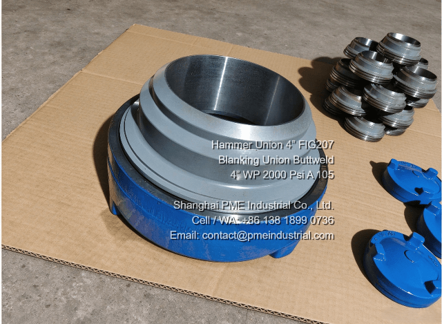
Figure 3: Machined butt weld bevel and internal step dimensions on the grey male sub.
Procurement & Quality Checklist for Regional Projects:
- Verify working pressure ratings (2,000 PSI CWP) against system operating parameters.
- Ensure material test reports (MTRs) complying with EN 10204 3.1 are provided for full batch traceability.
- Confirm dimensional compatibility with existing 4-inch line spreads in regional shipyards and plants.
For engineering drawings, detailed parameters, and material specifications on certified pipeline closures, visit Shanghai PME Industrial's official product portal to explore their complete 4 inch FIG 207 Blanking Union offering.
Looking for Certified Blanking Unions for Your Project?
Get direct manufacturer pricing, MTR documentation, and reliable shipping from Shanghai PME Industrial.
View Product Specification Page