2026年10月30日星期五

Sour Gas Service High Pressure Flowline Accessories (NACE MR0175 / 15K PSI)

Engineering Selection Guide: Metallurgy and Safety Standards for Sour Gas Flowline Accessories

In high-pressure well testing, hydraulic fracturing, and acid stimulation operations containing hydrogen sulfide (H2S), fluid handling equipment is exposed to severe environmental degradation. When hydrogen sulfide dissolves in water under working pressure, atomic hydrogen penetrates alloy steel matrices, triggering sulfide stress cracking (SSC) in non-compliant metals.

To prevent localized brittle fracture in temporary surface iron spreads, field engineers require certified Sour Gas Service High Pressure Flowline RAL6003 components heat-treated and controlled to strict API 6A and NACE MR0175 / ISO 15156 hardness limits.
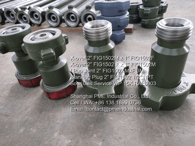
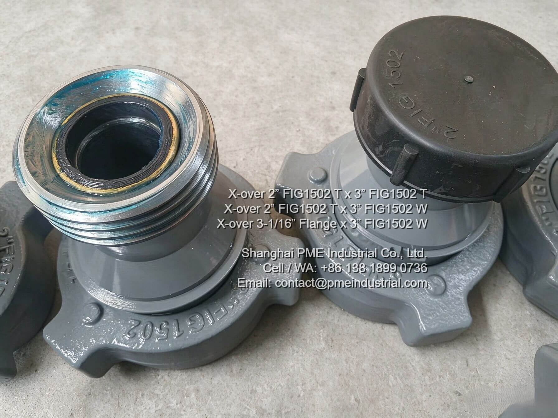
Sour Gas Service High Pressure Flowline RAL6003 crossover adapter sub

Figure 1: Forged 2" x 1" FIG1502 Crossover Adapter Sub Coated in RAL6003 Sour Service Color Code.

1. NACE MR0175 Hardness Control & Material Traceability

Selecting surface iron for sour service requires verifying chemical composition and heat treatment history beyond basic pressure ratings. Key metallurgical factors include:

  • Controlled Hardness Limits: Material must undergo specialized tempering to maintain hardness levels below 22 HRC (Rockwell C), mitigating hydrogen embrittlement susceptibility under load.
  • Seamless Forged Bodies: Components such as 3-meter pup joints and crossovers are forged without longitudinal weld seams to ensure uniform grain structure and stress distribution.
  • RAL6003 Color Identification: Applying sour gas service painted RAL6003 (Olive Green) finish provides visual confirmation on site, preventing cross-mixing with standard service iron (typically painted red or black).
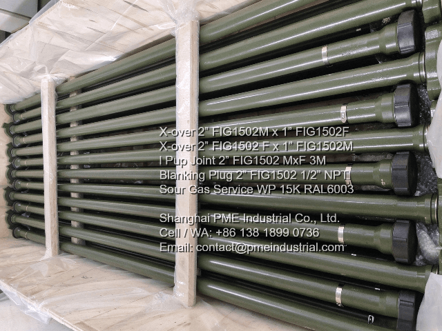
Sour Gas Service High Pressure Flowline RAL6003 integral pup joint 3 meters

Figure 2: Seamless Forged 2" FIG1502 MxF 3-Meter Integral Pup Joint for 15,000 PSI Sour Service.

2. Essential Accessories in Sour Service Surface Manifolds

A comprehensive sour service flowline setup relies on several core components engineered to operate seamlessly at 15,000 PSI CWP:

  • Size Crossover Adapters: Enable smooth transitions between 2" and 1" FIG1502 lines in choke manifolds and fluid sampling lines.
  • Integral Pup Joints: Provide straight fluid conduit runs with integral hammer union connections, minimizing erosion points.
  • Tapped Blanking Plugs: Feature center-drilled 1/2" Female NPT ports, allowing direct installation of pressure sensors for continuous real-time data monitoring in sour spreads.
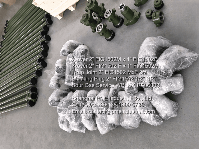
Sour Gas Service High Pressure Flowline RAL6003 blanking plug with 1/2 NPT port

Figure 3: 2" FIG1502 Blanking Plug with Integrated 1/2" NPT Port for Pressure Gauge Mounting.

Quality Documentation Checklist for Procurement Officers:

  • Require 3.1 Material Test Reports (MTRs) detailing chemical analysis and NACE hardness verification.
  • Confirm 100% hydrostatic shell pressure testing certificates (tested to 22,500 PSI).
  • Ensure thread protection caps are installed on male union ends to protect critical sealing surfaces during transport.

For comprehensive engineering drawings, material specifications, and quality test documentation on API 6A certified flow iron, visit Shanghai PME Industrial's official page to explore their full Sour Gas Service High Pressure Flowline RAL6003 product line.

Need Certified Sour Gas Flowline Iron & Documentation?

Get direct manufacturer pricing, MTR documentation, and custom thread configurations from Shanghai PME Industrial.

View Product Specification Page
2026年10月28日星期三

API 7K Rotary Hose 4" Grade E 7500 PSI in Drilling Rig Mud Lines

Engineering Guide: Selecting High-Pressure Rotary Drilling Hoses for Mud Circulation

In high-pressure drilling spreads, maintaining steady mud circulation between the standpipe manifold and the top drive or swivel requires robust, flexible high-pressure conduits. These lines operate under continuous mechanical pulsation from triplex mud pumps, high-velocity abrasive slurry flow, and unpredictable atmospheric exposure.

Deploying an API Spec 7K certified Rotary Hose 4 Grade E 7500 PSI ensures necessary flexibility while guaranteeing high structural resistance against pressure surges up to 7,500 PSI working pressure.

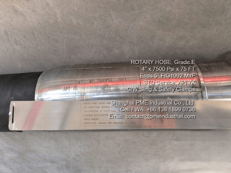
Rotary Hose 4 Grade E 7500 PSI stainless steel serialized nameplate

Figure 1: Stainless Steel Serialized Identification Nameplate for API 7K Traceability.

1. Structural Composition & Reinforcement Plies

Standard industrial rubber hoses lack the burst resistance and fatigue endurance required for heavy oilfield service. API 7K Grade E specifications mandate specialized multi-layer construction:

  • Inner Liner: Oil-resistant Nitrile (NBR) formulated to withstand both water-based and synthetic oil-based drilling muds without swelling.
  • Steel Wire Reinforcement: Multiple alternating spiral layers of heavy-gauge, high-tensile steel wire cable designed to absorb tensile strain during top drive vertical movement.
  • Outer Sheath: Weathering, ozone, and flame-resistant Neoprene (CR) compound protecting internal steel plies from ocean salt-spray or desert UV degradation.
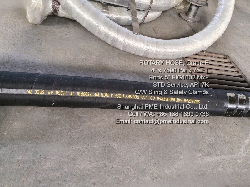
Rotary Hose 4 Grade E 7500 PSI continuous body marking

Figure 2: API Spec 7K Continuous Layline Body Marking Showing Grade E Working Pressure Ratings.

2. Rotary Hose vs. Vibrator Hose Application Differences

While both configurations share the same technical rating under a 4" ID Rotary Hose 4 Grade E 7500 PSI specification, their physical deployment locations dictate different length requirements:

  • Rotary Drilling Hose (Kelly Hose): Long flex-lines (typically 45ft to 90ft) connecting the derrick standpipe to the traveling block or top drive.
  • Vibrator Hose: Short flexible jumpers (typically 10ft to 30ft) connecting the mud pump discharge manifold to the standpipe, absorbing harmonic pump vibrations.
Rotary Hose 4 Grade E 7500 PSI packed on heavy duty steel spools for export shipment

Figure 3: Heavy-Duty Reel Packaging Prepared for International Drilling Rig Shipping.

Key Inspection Parameters for Rig Maintenance Personnel:

  • Check that end connections are integrally vulcanized to prevent coupling blow-off under pressure surges.
  • Ensure minimum bend radius limits are respected during derrick installation to avoid kink-induced fatigue.
  • Verify factory hydrostatic test certification (15,000 PSI for Grade E lines) prior to field commissioning.

For complete technical drawings, custom end-fitting options (NPT threads, Hammer Unions, or API Flanges), and test certificates, visit Shanghai PME Industrial's official engineering center to explore their full Rotary Hose 4 Grade E 7500 PSI specification page.

Inquire About API 7K Drilling Hoses & Custom Lengths

Get direct manufacturer pricing, material test reports, and global logistics support from Shanghai PME Industrial.

Visit Product Specification Page

2026年10月27日星期二

2" FIG 1502 Male Blind Subs in High-Pressure Surface Flowlines

Engineering Considerations for High-Pressure Flowline Blanking Subs

In high-pressure well servicing, hydraulic fracturing spreads, and flowback manifold systems operating up to 15,000 PSI, safely dead-ending auxiliary lines is a mandatory operational routine. Choosing between a standard solid blind cap and a tapped blind sub directly influences both real-time data logging capabilities and rig-down safety protocols.

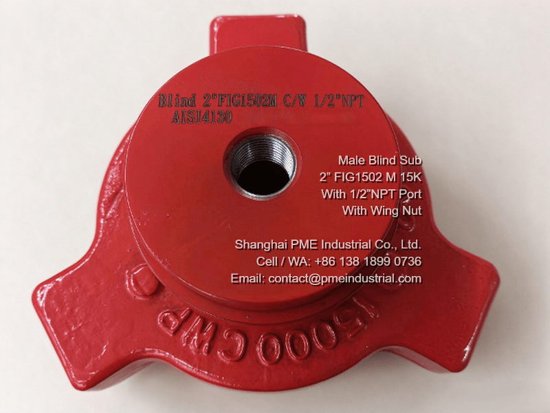
Deploying a precision-machined Male Blind Sub 2 FIG 1502 1/2 NPT allows field crews to isolate terminal female hammer union connections while maintaining direct fluid access for pressure gauges or bleed-off needle valves.

Male Blind Sub 2 FIG 1502 1/2 NPT with serial number

Figure 1: Forged Male Blind Sub 2 FIG 1502 1/2 NPT with Unique Traceable Serial Numbering.

1. Threaded 1/2" NPT Tapping vs. Solid Blind Sub Construction

Understanding the mechanical distinctions between tapped and solid blind subs prevents line retrofitting on site:

  • Tapped NPT Version: Features a center-drilled, female 1/2" NPT port. This allows field engineers to thread electronic pressure transducers, sampling valves, or pressure gauges directly into line ends without altering permanent manifold blocks.
  • Solid Version: Manufactured as a continuous, un-drilled forging. It serves purely as a structural fluid barrier where auxiliary instrumentation is strictly prohibited.
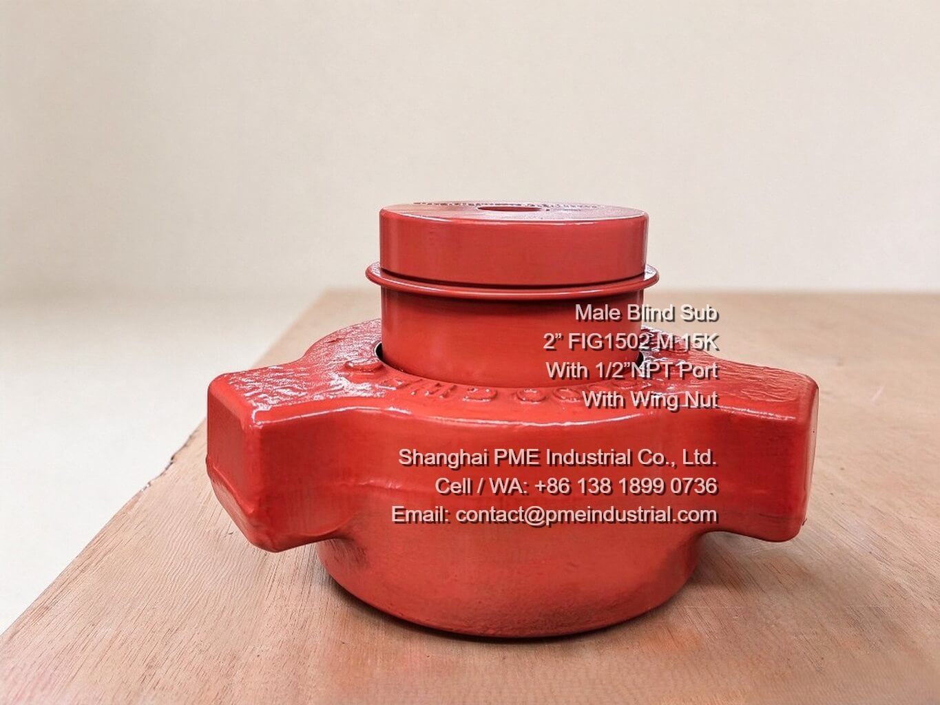
Male Blind Sub 2 FIG 1502 1/2 NPT complete with wing nut

Figure 2: Complete Male Blind Sub Assembly with Heavy-Duty ACME Wing Nut.

2. Field Safety Benefits During Line Breakdown

One primary safety hazard during rig-down operations is trapped residual pressure behind hammer union subs. When using a Male Blind Sub 2 FIG 1502 1/2 NPT equipped with an attached bleed valve, operators can verify and vent zero trapped pressure before striking wing nuts with sledgehammers, significantly reducing blowout risks.

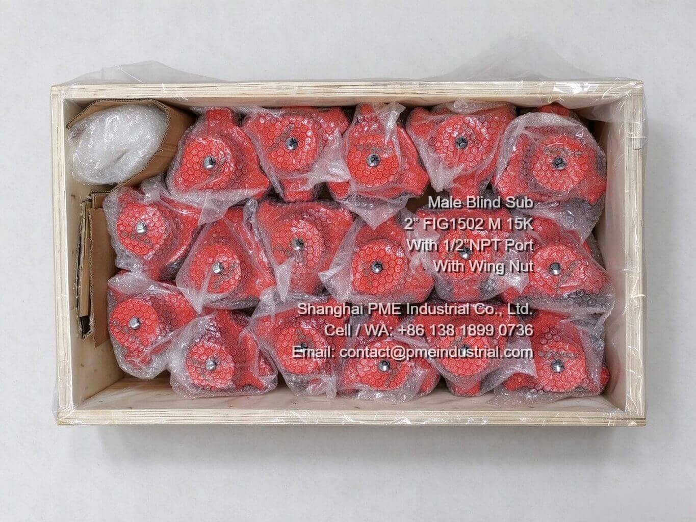
Male Blind Sub 2 FIG 1502 1/2 NPT packaged for shipment

Figure 3: Export Wooden Crate Packaging for High-Pressure Flowline Components.

Quality Inspection Checklist for High-Pressure Isolation Subs:

  • Ensure bodies are forged from heat-treated AISI 4130 alloy steel (15,000 PSI CWP).
  • Verify NACE MR0175 compliance for sour gas (H2S) service lines.
  • Require 3.1 Material Test Reports (MTRs) and Hydrostatic Test Certificates.

For comprehensive dimensional specifications, heat treatment details, and hydrostatic test documentation on forged high-pressure components, visit Shanghai PME Industrial's official page to explore their full Male Blind Sub 2 FIG 1502 1/2 NPT range.

Looking for Certified 15K PSI Flowline Blanking Subs?

Get direct manufacturer pricing, custom thread options, and full material traceability from Shanghai PME Industrial.

View Product Specification Page
2026年10月26日星期一

Metric 90 Degree Female Swivel Hose Fittings in Oilfield Hydraulic Piping

Key Considerations for Hydraulic Hose End Selection in High-Pressure Rig Operations

In hydraulic fluid power transmission across land drilling rigs, selecting the proper hose termination profile is essential for preventing downtime caused by fluid loss under severe mechanical vibration. For field engineers and rig maintenance crews operating in Central Asia, configuring high-pressure hose assemblies requires balancing working pressure ratings, thread standards, and space constraints in tight manifold spaces.

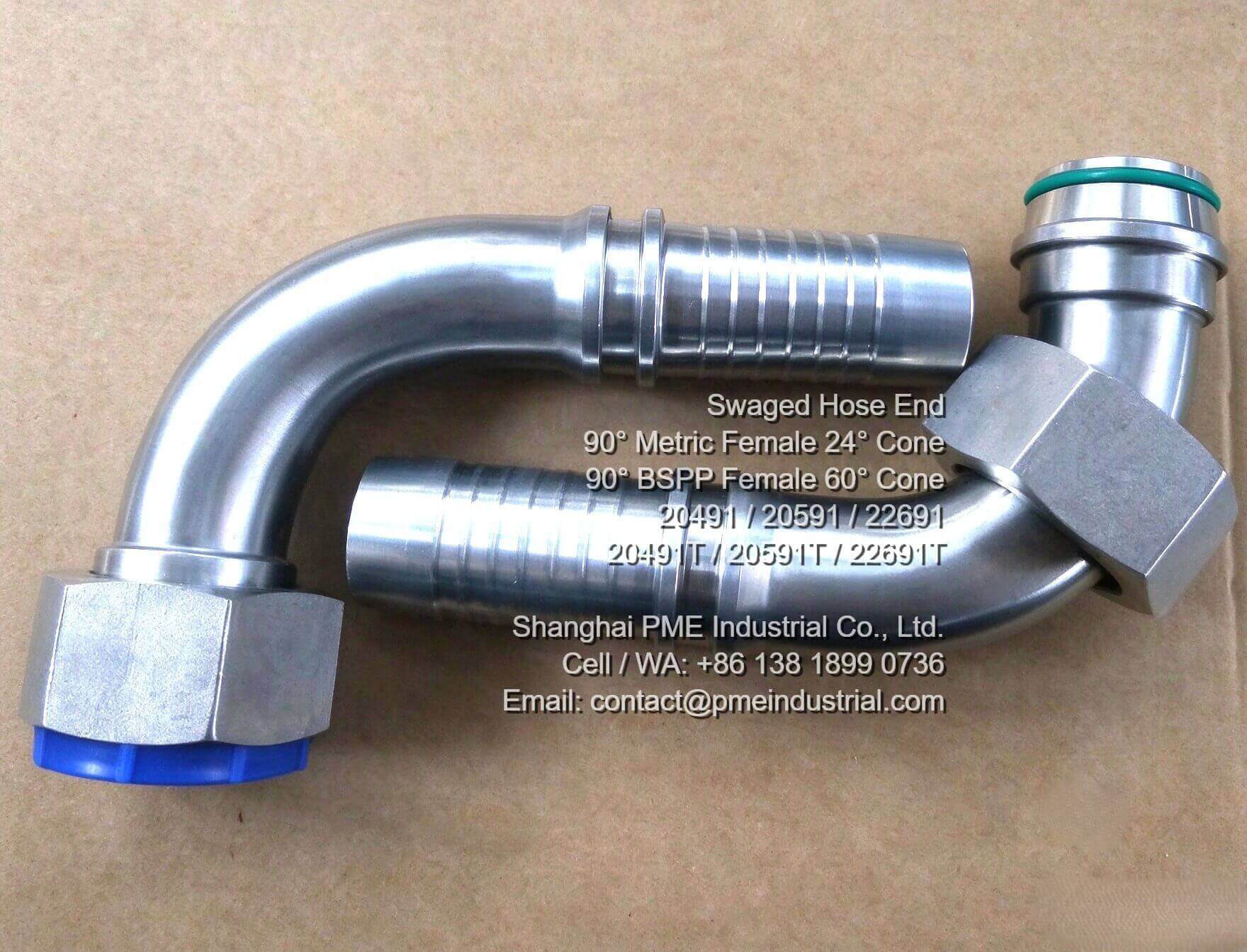
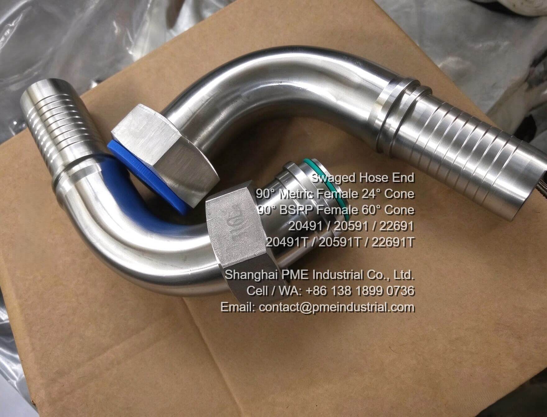
Among the most versatile elbow configurations, the metric 90 degree female swivel hose fitting provides a 90-degree directional transition while enabling 360-degree rotational alignment prior to final tightening.

metric 90 degree female swivel hose fitting 20491 light series

Figure 1: Model 20491 Light Series Metric 90° Female Swivel Hose Fitting.

1. Distinguishing Light Series (20491) vs. Heavy Series (20591) Metric Swivels

When specifying a 24° cone metric female connection, technicians must correctly differentiate between ISO/DIN light series and heavy series configurations to ensure physical thread engagement and pressure containment:

  • Light Series (Model 20491): Features smaller thread pitch dimensions and tube OD sizing, making it suitable for standard hydraulic lines on auxiliary drilling machinery (such as part numbers 20491-30-12T, 20491-36-16T, and 20491-52-24T).
  • Heavy Series (Model 20591): Designed with heavier wall thickness and robust thread dimensions built to handle high-pressure pulsations on mud pumps and blow-out preventer (BOP) control units (such as part numbers 20591-20-06T, 20591-30-12T, and 20591-52-24T).
metric 90 degree female swivel hose fitting 20591 heavy series

Figure 2: Model 20591 Heavy Series 24° Cone Swivel Hose Fitting for Heavy Duty Hydraulic Lines.

2. Application of BSPP 60° Cone Swivels (22691 Series)

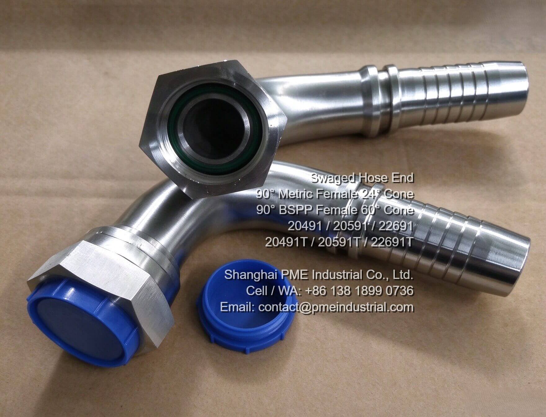
In addition to metric systems, British Standard Pipe Parallel (BSPP) threads with 60° cone seats remain widely installed in European and Asian hydraulic equipment. Utilizing a custom metric BSPP hose tail for Central Asia oilfield setups allows seamless field maintenance without re-piping original equipment manifolds. Model 22691 swaged fittings (e.g., 22691-08-08, 22691-10-10, and 22691-16-16) provide consistent metal-to-metal sealing across 1/2", 5/8", and 1" line sizes.

BSPP 60 degree cone 90DEG female swivel hose tail model 22691

Figure 3: Model 22691 BSPP 60° Cone 90° Female Swivel Hose Connector.

Procurement Checkpoints for Field Technicians:

Before finalizing crimping specifications for high-pressure hose lines, verify the following:

  1. Confirm thread specification and pitch (Metric ISO vs. BSPP).
  2. Match the exact hose tail size to inner hose diameter (e.g., 3/8", 1/2", 3/4", 1", 1-1/2").
  3. Ensure compatibility with targeted working pressure limits and winter temperature minimums.

For comprehensive dimensional charts, technical drawings, and certified manufacturing details on high-pressure fluid fittings, visit Shanghai PME Industrial's official engineering center to explore their complete line of hydraulic hose fitting for oil drilling solutions.

Need Certified Oilfield Hydraulic Hose Fittings?

Request technical datasheets, MTRs, and direct manufacturer pricing directly from Shanghai PME Industrial.

Visit Product Specification Page
2026年10月22日星期四

How to Choose the Right FIG 1502 Crossovers for High-Pressure Oilfield Flowlines

Optimizing High-Pressure Flowlines with FIG 1502 Crossovers

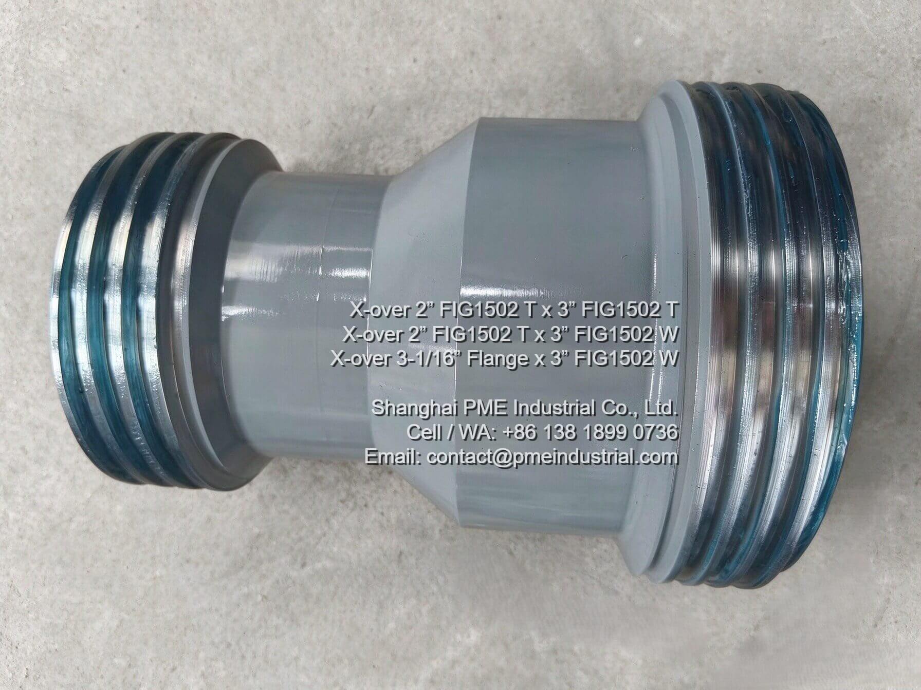
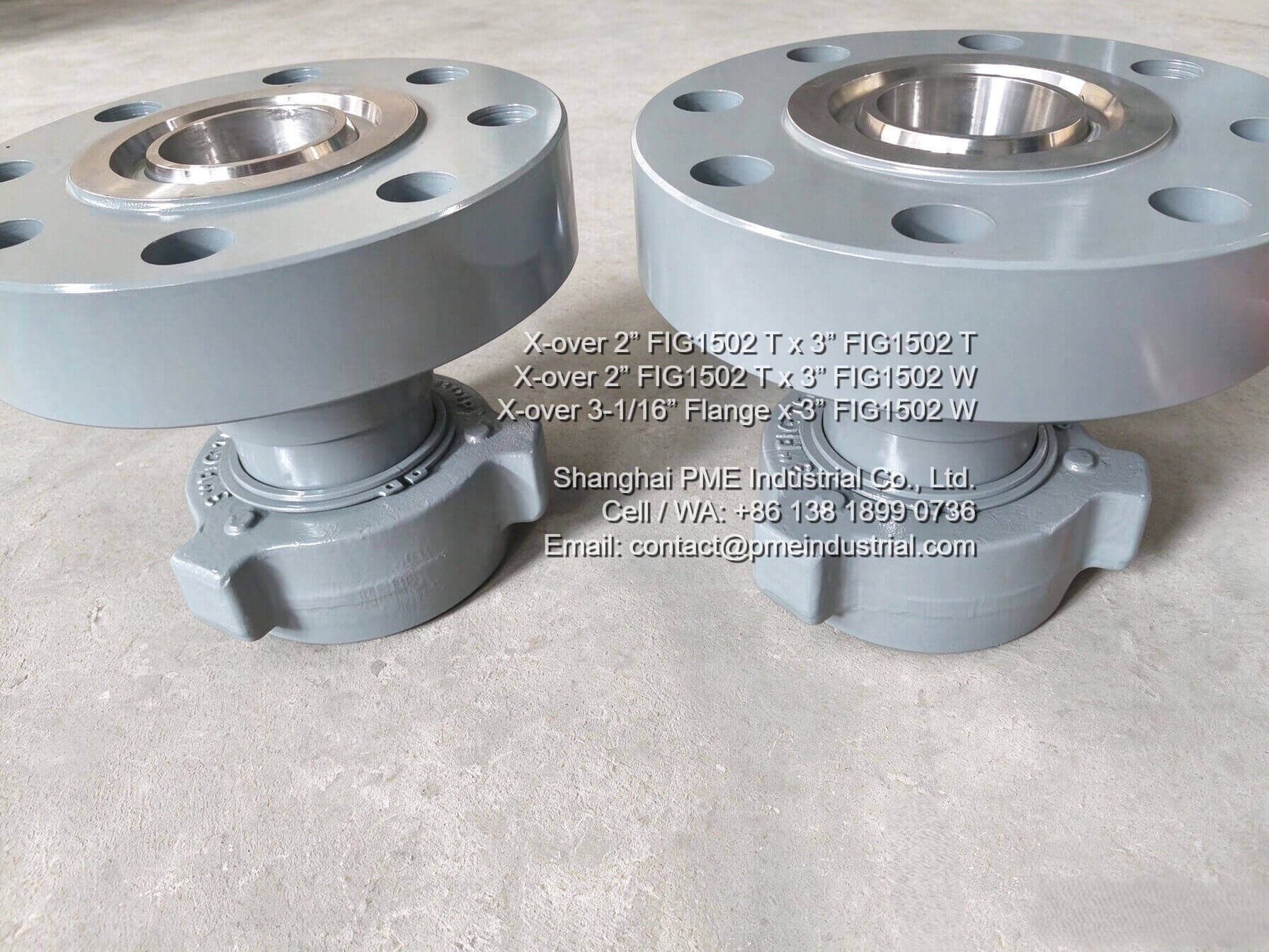
In high-pressure well testing, fracturing, and cementing operations, maintaining seamless fluid control across varied pipe dimensions is critical. Standardized hammer union fittings provide speed and flexibility, but when transitions between different diameters or connection ends are required, a reliable FIG 1502 Crossover becomes indispensable.

2 Inch to 3 Inch FIG 1502 Threaded Crossover Adapter

Figure 1: 2" FIG 1502 Threaded x 3" FIG 1502 Threaded Crossover Adapter for high-pressure systems.

Key Considerations for Selecting Crossovers

Choosing the right adapter requires checking several core specifications to prevent leaks and structural failures under extreme pressure:

  • Pressure Rating: Ensure the component matches the 15,000 PSI (cold working pressure) rating typical for FIG 1502 configurations.
  • Material Quality: Look for high-strength forged alloy steel that complies with API 6A manufacturing standards.
  • End Configurations: Verify end options such as Male x Female, LP Threaded, or Flanged depending on line requirements.
  • Sour Service Compliance: For environments containing H2S, spec-compliant materials conforming to NACE MR0175 are mandatory.
2 Inch Threaded to 3 Inch Wing Fig 1502 Crossover Fitting

Figure 2: Precision-machined 2" Threaded x 3" Wing Crossover Fitting ensuring secure integration.

Why Precision Machining Matters

Because crossovers act as critical transition joints, precise thread alignment and surface finishing are crucial. Poorly fitted adapters can accelerate wear from abrasive fluids or cause localized stress concentration during pressure spikes.

3-1/16 Inch Flange to 3 Inch FIG 1502 Flanged Crossover

Figure 3: Heavy-duty 3-1/16" Flange x 3" FIG 1502 Wing Flanged Crossover for oilfield setups.

Need custom dimensions or full technical specifications for high-pressure flowline equipment? Explore the complete specs and manufacturing standards on the official PME FIG 1502 Crossover Product Page.

To learn more about high-pressure fluid control products and industrial piping components, visit PME Industrial.

2026年10月20日星期二

API 16C 3-1/8" 5K Choke and Kill Manifold Systems

Engineering Insights: Optimizing Well Control with API 16C Choke and Kill Manifold Systems

Published by Shanghai PME Industrial Technical Team | Well Control Engineering Insights

During high-pressure oil and gas drilling operations, managing formation pressure surges and executing safe kick containment require robust surface infrastructure. Integrating a dependable Choke and Kill Manifold into the surface BOP spread ensures that drilling crews can circulate out influx fluids under precise backpressure regulation.

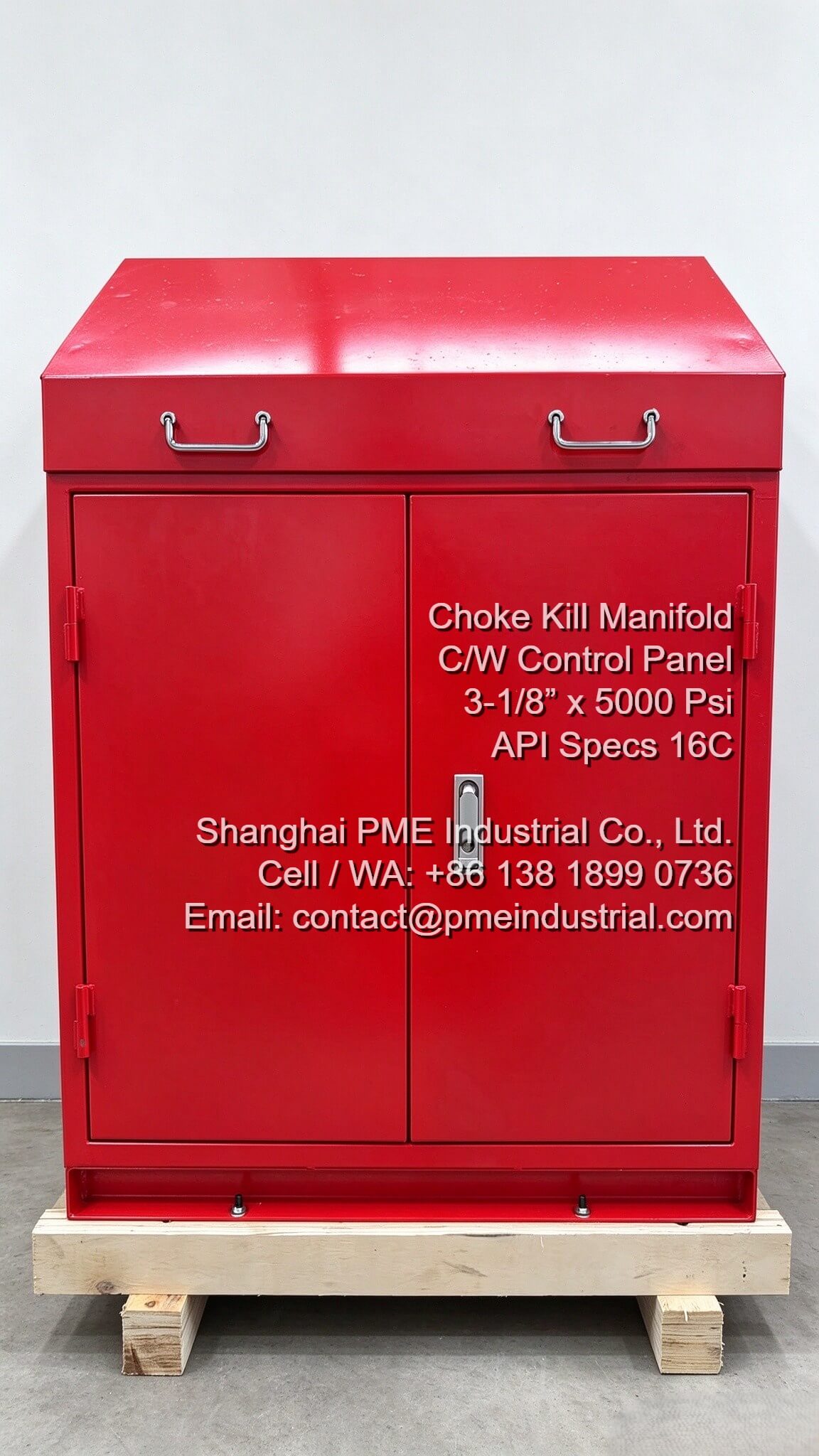
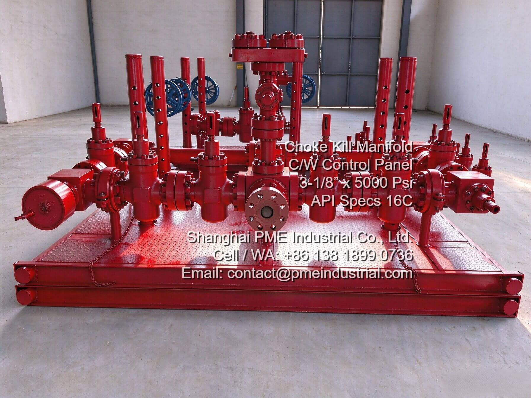
3 1 8 5K Choke Kill Manifold skid mounted assembly for well control

Figure 1: Skid-mounted 3-1/8" 5K choke and kill manifold assembly tested to 7,500 PSI.

1. Coordinated Functions of Choke and Kill Flowlines

The choke line manages regulated fluid discharge through adjustable chokes and high-integrity gate valves, protecting casing strings from over-pressurization. Simultaneously, the kill line provides a direct injection route for high-density kill mud backed by check valve barriers. Deploying an API 16C certified choke manifold for oil and gas guarantees structural integrity under aggressive H2S environments.

Remote hydraulic control panel for choke manifold operational regulation

Figure 2: Remote pneumatic-hydraulic control panel for safe remote regulation.

2. Remote Operation and Hydraulic Hose Integrity

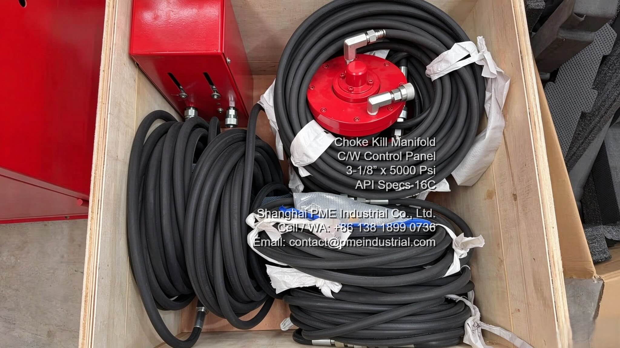
Operating high-pressure flowlines requires isolation from hazardous rig floor zones. Utilizing a dedicated control panel for choke manifold systems enables engineers to adjust choke apertures smoothly from the doghouse. Combined with armored hydraulic control hose bundles, these setups maintain responsive actuation during emergency well control.

Choke kill manifold control panel hydraulic hose lines packed in wooden crate for export dispatch

Figure 3: Export crate packing of high-pressure control hose lines and accessories.

Conclusion

Investing in fully traceable, hydro-tested well control manifold packages ensures operational safety and regulatory compliance. To review complete technical data and specifications, visit the official Shanghai PME Industrial Product Page.

2026年10月16日星期五

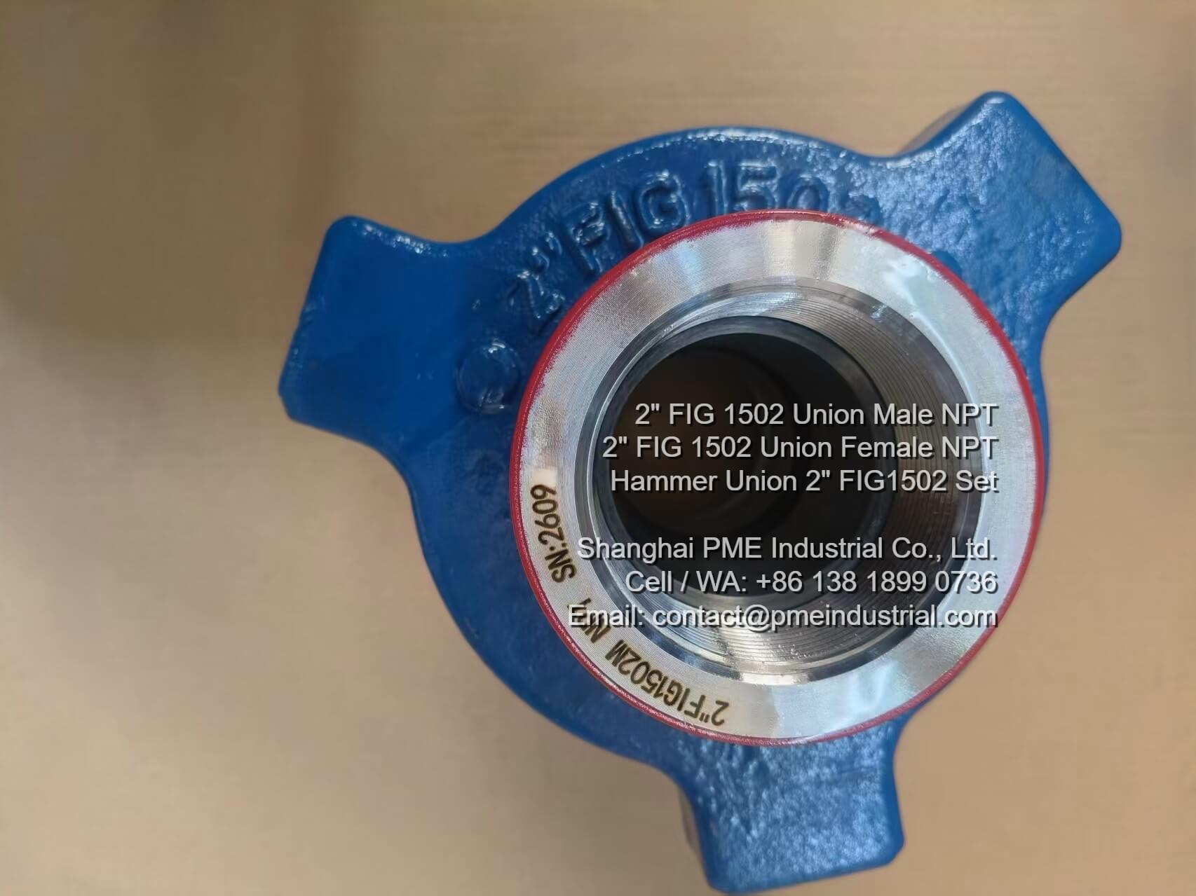
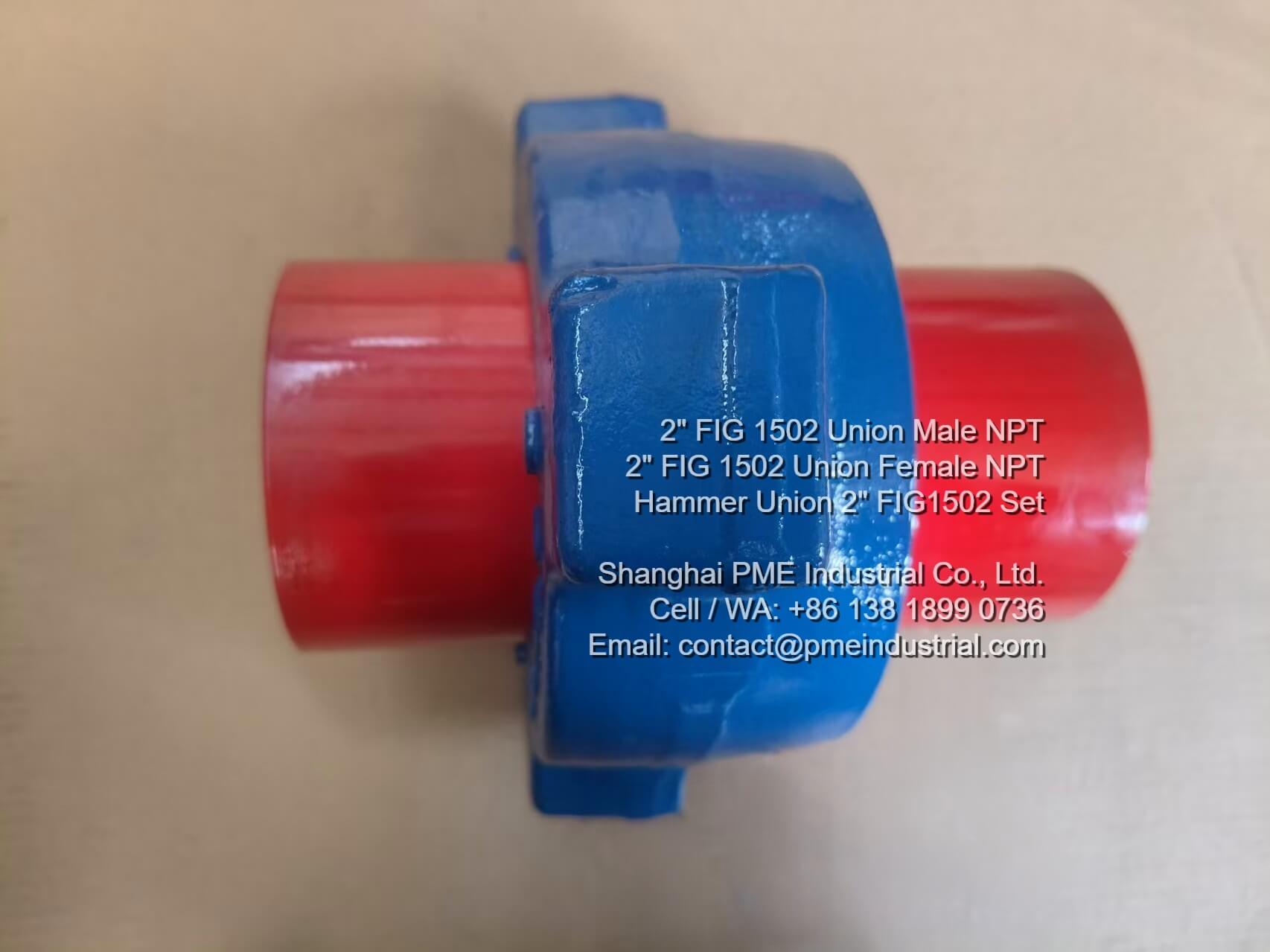
Hammer Union 2 Inch FIG1502 Threaded Male Female Wing Nut

2 Inch FIG1502 Threaded Hammer Union with Male, Female, and Wing Nut Configurations

HIGH-PRESSURE MANIFOLDS | 15,000 PSI W/P | FIG1502 SERVICE | RECENT AFRICAN OILFIELD DISPATCH

High-Pressure Fluid Connection Demands in African Oilfield Projects

In high-pressure oil and gas extraction, cementing, and well stimulation spreads across active African oilfields, pipeline integrity under intense pressure surges is vital. Operations require reliable quick-make union connections that can withstand cyclical mechanical loads without leaking. Sourcing dependable hardware like a Hammer Union 2 Inch FIG1502 ensures structural security across high-vibration drilling spreads and temporary surface lines.

Shanghai PME Industrial delivers engineered fluid components designed for demanding service ratings. Our precision-forged fittings provide the mechanical strength and pressure containment necessary for modern oilfield fluid control architectures.

Technical Specifications: FIG1502 Threaded Union Components

Every FIG1502 Threaded Hammer Union assembly is manufactured from high-strength alloy steel, heat-treated to match strict sour gas and standard oilfield specifications. Below are standard technical parameters for our 2-inch line:

Specification Parameter Technical Details
Nominal Size & Model 2 Inch Nominal Size / FIG 1502 Series
Working Pressure Rating 15,000 PSI Cold Working Pressure (103.4 MPa)
Assembly Components Threaded Male Sub, Female Sub with Lip Seal, and Hammer Wing Nut
End Connections Line Pipe Thread (NPT / LP) or Butt-Weld Options
Material & Quality Control Forged Alloy Steel, Fully Traceable with MTR Documentation

Performance Advantages of Male, Female, and Wing Nut Assemblies

The design of a 2 Inch FIG1502 Male Female Wing Nut assembly provides distinct mechanical benefits on the rig floor:

  • Robust Sealing Mechanism: The FIG1502 Hammer Union incorporates a resilient lip seal that acts as a primary barrier against fluid leakage under high-frequency pressure fluctuations.
  • Rapid Make-Up: The heavy-duty wing nut engages smoothly with the threaded male and female subs, allowing rig crews to couple lines quickly using standard hammers.
  • High-Pressure Capability: Built specifically to handle 15,000 PSI service, this 2 Inch FIG1502 Union safeguards critical cementing and fracturing manifolds.
2 Inch FIG1502 Union Marking Serial Number and traceability details
Traceability & Serial Marking

Embossed pressure rating and serial number on a finished Hammer Union 2 Inch FIG1502 unit.

Hammer Union 2 Inch FIG1502 Threaded Assembly complete with wing nut
Complete Threaded Assembly

Assembled Threaded Hammer Union FIG1502 ready for pressure testing.

2 Inch FIG 1502 UNION Male Female NPT threaded connection profile
Male and Female Subs

Precision-machined NPT threads on a 2 Inch FIG1502 Male Female Wing Nut set.

Case Spotlight: Recent Completion and Dispatch for African Clients

Meeting project delivery timelines is critical when oilfield operators require replacement components for active drilling campaigns. Shanghai PME Industrial recently completed a major production batch of high-pressure fittings ordered by an established oilfield service provider in Africa.

The order featured multiple configurations of the Hammer Union 2 Inch FIG1502, complete with matching threaded male subs, female subs, and durable wing nuts. Following rigorous dimensional checks and quality inspection, the entire batch has been successfully finalized and prepared for export shipment to support regional well servicing operations.

Why Global Oilfield Operators Choose PME Industrial

As a trusted partner in international oilfield supply networks, Shanghai PME Industrial focuses on delivering verifiable quality and dependable export service:

  • Full Material Traceability: Complete Material Test Reports (MTRs) and quality inspection certificates accompany every batch.
  • Strict Pressure Compliance: Designed to meet or exceed industry standards for 15,000 PSI high-pressure service.
  • Reliable Export Logistics: Secure packaging designed to withstand international transit to African and global oilfields.

Inquire About FIG1502 Hammer Union Inventory

Contact our engineering sales team today to request technical datasheets, MTR documentation, or custom pricing for your high-pressure manifold projects.

Industrial Flow Control & High-Pressure Equipment

Contact Engineering Sales

2026年10月15日星期四

API 16D 5000psi Flame Resistant SS Armoured BOP Control Hose

Engineering Insights: Why API 16D Compliance Matters for BOP Control Hose Assemblies

Published by Shanghai PME Industrial Technical Team | Well Control Equipment Insights

In offshore and onshore drilling campaigns across Europe, blow-out preventer (BOP) hydraulic control systems represent the primary defense line for well control management. Delivering reliable hydraulic pressure during emergency events requires an uncompromising, high-integrity BOP Control Hose built to withstand mechanical wear, high operating temperatures, and severe internal pressure surges.

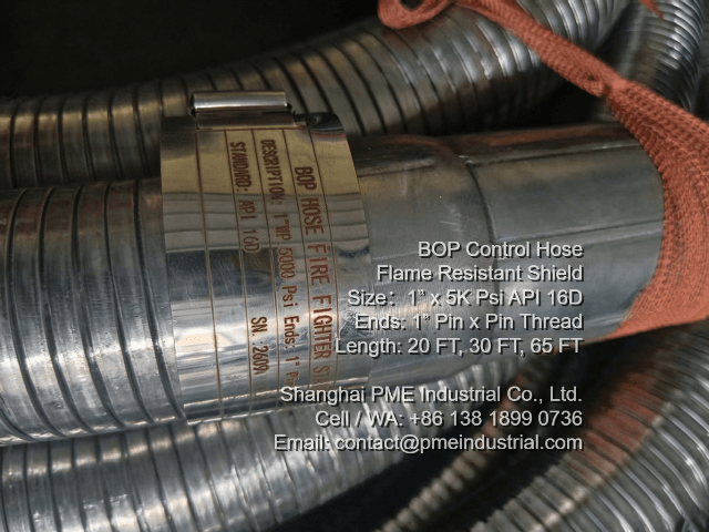
BOP Control Hose Nameplate showing API 16D 5000psi certification and serial details

Figure 1: Traceability nameplate indicating API 16D compliance and 5000 PSI working pressure rating.

1. The Role of Fireproof Shielding and Stainless Steel Armouring

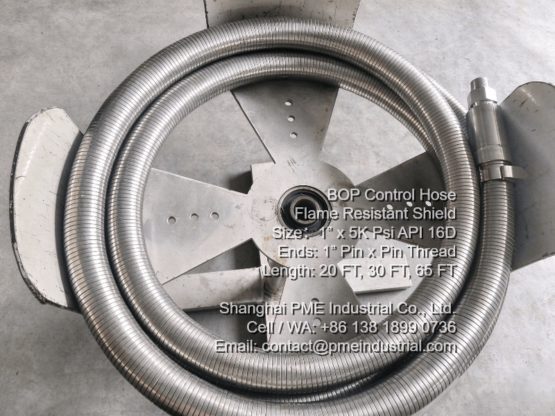
Standard hydraulic lines can degrade rapidly when exposed to open flame. Incorporating a specialized API 16D BOP Hose featuring an outer fireproof insulation jacket and an interlocking stainless steel armour layer ensures that hydraulic actuation circuits remain functional under extreme thermal conditions (meeting API Spec 16D flame test requirements of 704°C for 5 minutes).

BOP Control Hose Flame Resistant Shield coiled neatly in workshop after pressure testing

Figure 2: Factory pressure testing and coiling of flame-resistant hose bundles.

2. Standardized Lengths and European Rig Integration

When supplying European drilling contractors, dimensional precision and standardized assembly lengths are critical:

  • Length Options: Widely deployed in 20 FT, 30 FT, and 65 FT continuous configurations to fit diverse rig floor layouts.
  • End Connections: Equipped with 1" Pin x Pin NPT threaded fittings for direct coupling to accumulator units.
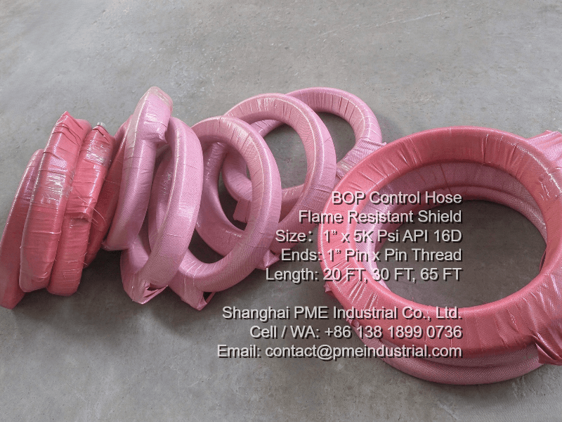
  • Export Packaging: Packed securely in wooden cases to prevent transit damage during overseas shipping.
SS Armoured API 16D BOP Hose packed securely in wooden cases for container export to Europe

Figure 3: Secure crate packaging of stainless-armoured hose assemblies ready for export.

Conclusion

Investing in certified well control components ensures operational safety and regulatory compliance. To review full technical datasheets and certification details, visit the official Shanghai PME Industrial Product Page.

2026年10月13日星期二

Fuel Oil Hose 300 PSI for Southeast Asia Oilfield Supply

Engineering Field Report: Selecting Fuel Oil Hoses for Remote Well Site Logistics

Published by Shanghai PME Industrial Technical Team | Oilfield Fluid Handling Insights

Maintaining continuous power generation and auxiliary equipment operation in remote oilfield spreads requires dependable fuel supply logistics. In tropical exploration environments like Southeast Asia, operators need flexible, oil-resistant fluid lines capable of handling daily diesel and lubricant transfer without premature degradation. Specifying a reliable Fuel Oil Hose is essential for smooth rig operations.

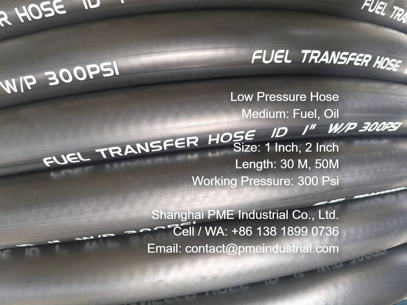
Fuel Oil Hose 300 Psi 1 Inch Hose Marking for oilfield transfer lines

Figure 1: Clear specification and 300 PSI working pressure embossing on 1 inch fuel oil lines.

1. Pressure Balance and Material Endurance

While high-pressure mud lines require steel reinforcement, daily fuel tank filling and generator routing benefit from lightweight, highly flexible 300 PSI hoses. Utilizing a specialized synthetic rubber tube resistant to aromatic hydrocarbons ensures that the inner core remains structurally intact under constant fluid exposure, while outer covers withstand UV exposure and muddy terrain.

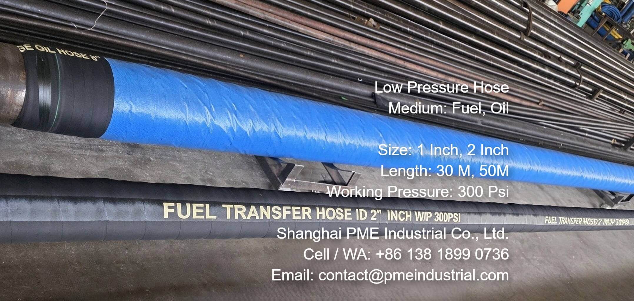
Fuel Oil Hose 300 Psi 2 Inch Hose Production Line manufacturing batch

Figure 2: Precision extrusion and textile reinforcement process for 2 inch 300 PSI hose lines.

2. Field Delivery Spotlight: Rapid Dispatch to Southeast Asia

In a recent project for an oilfield service contractor in Southeast Asia, custom continuous roll lengths were provided to streamline site installation:

  • 1 Inch (50M Roll): Tailored for mobile refilling units and generator fuel supply.
  • 2 Inch (30M Roll): Configured for higher volumetric transfer between storage tanks.
  • Fumigation-Free Crate Packaging: Ensured zero delays during maritime port clearance.
Fuel Oil Hose 300 Psi Export Fumigation Free Wooden Crate ready for dispatch

Figure 3: Secure wooden crate packaging designed for overseas transit to well sites.

Conclusion

Choosing the right hose specification ensures operational safety and minimizes rig downtime. For technical datasheets, full sizing tables, and global delivery inquiries, visit the official Shanghai PME Industrial Product Page.